Shell parting-line location
Record the acceptance method for shell parting-line location. Include the mating CAD, load or environment as relevant; do not rely on nominal part dimensions alone.
The catalogue includes a controller shell photograph. Its visible cutouts and curved gripping surfaces put surface appearance, button travel and assembly gap control at the centre of tooling discussions.
The visible geometry gives context. Application-specific decisions still begin with a drawing.
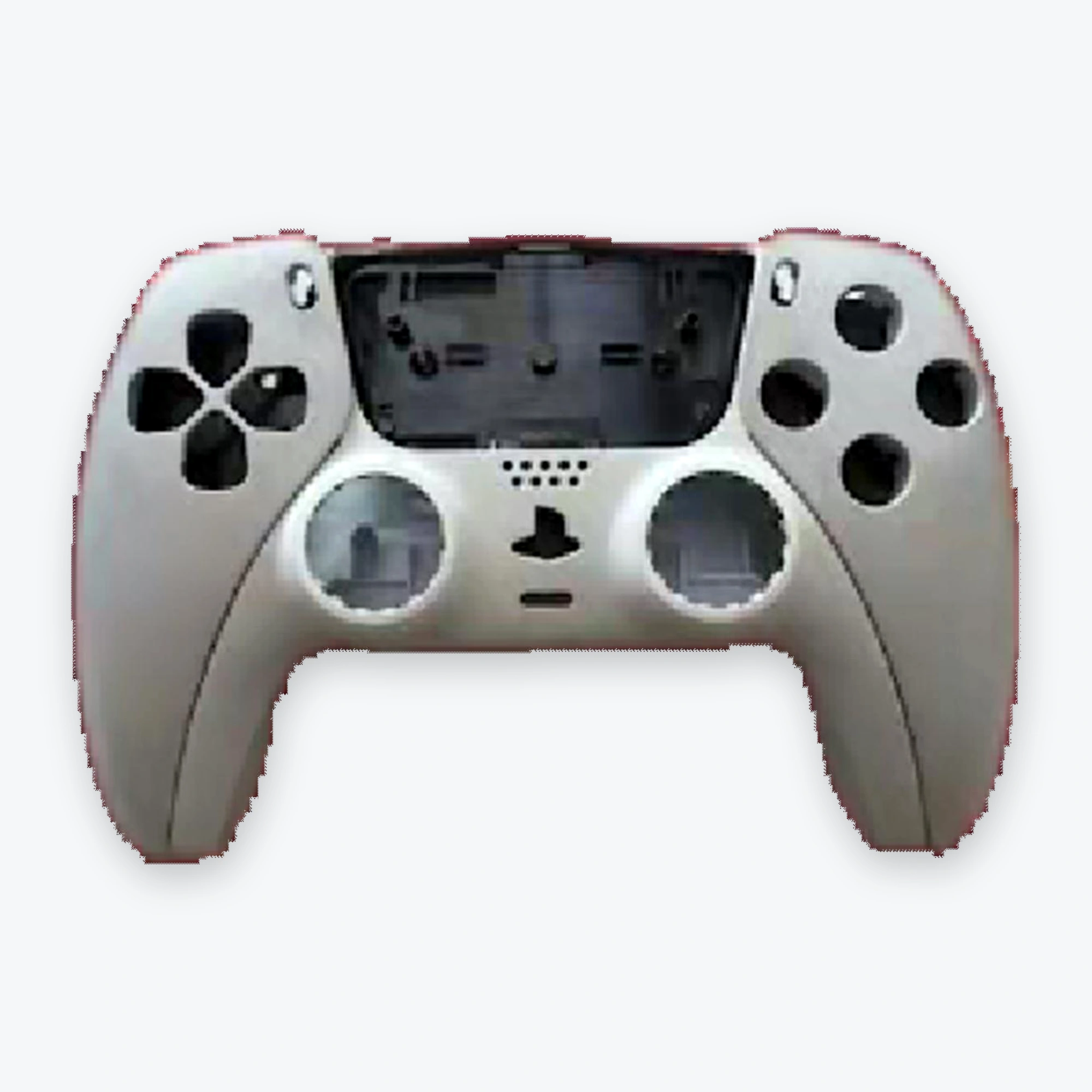
The catalogue includes a controller shell photograph. Its visible cutouts and curved gripping surfaces put surface appearance, button travel and assembly gap control at the centre of tooling discussions.
For a consumer electronics OEM and mechanical designer, a moulded component is not approved by appearance alone. The geometry that positions it, the way it is fastened and the surrounding environment should be understood before the tooling choice is fixed.
The photograph identifies the category. It does not define a material grade, drawing revision, nominal dimensions or catalogue number. Those details belong to the approved project documents.
A specification table is useful only when it separates what is documented from what still needs an engineering decision.
| Parameter | Definition for this product category |
|---|---|
| Photographed example | game controller outer shell and button enclosure |
| Primary application | gamepad shells, controls and electronic device enclosures |
| Part material | Confirm specified resin grade and supplier with RFQ |
| Nominal dimensions | According to the customer drawing |
| Tolerance specification | Project-specific; select critical datums and acceptance plan |
| Surface treatment | According to approved appearance and finish reference |
| Mold cavities / process settings | Determined after DFM and volume review |
| Quotation basis | CAD, drawing, annual volume, destination and finishing |
| Sample and production release | Subject to tool trial and signed approval |
← Scroll table horizontally on smaller screens →
Design inputs for consistent grip feel, assembly gaps and actuator clearances.
Record the acceptance method for shell parting-line location. Include the mating CAD, load or environment as relevant; do not rely on nominal part dimensions alone.
Record the acceptance method for button travel and clearance. Include the mating CAD, load or environment as relevant; do not rely on nominal part dimensions alone.
Record the acceptance method for boss strength and screw retention. Include the mating CAD, load or environment as relevant; do not rely on nominal part dimensions alone.
Record the acceptance method for colour and tactile surface. Include the mating CAD, load or environment as relevant; do not rely on nominal part dimensions alone.
Record the acceptance method for drop and handling loads. Include the mating CAD, load or environment as relevant; do not rely on nominal part dimensions alone.
A part can satisfy its own drawing and still perform poorly in the next assembly.
{esc(p["checks"][0])}
{esc(p["checks"][1])}
{esc(p["checks"][2])}
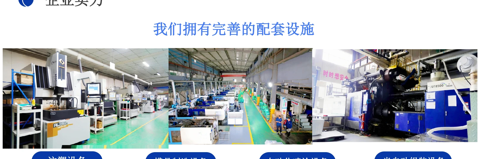
The sampling and inspection plan should be agreed before large production lots are scheduled.
Confirm actual part use, critical interfaces and finish expectations.
Discuss likely gate, parting line, ejector and cooling constraints.
Check fit, surface and characteristics against an agreed sample and drawing.
Document ordering quantities, packing method, process controls and revision changes.
A useful RFQ gives enough information to distinguish a tooling investment from a repeat part purchase.
| Buyer question | Practical answer |
|---|---|
| Can you guarantee a material or tolerance? | Not without the target geometry, approved resin and drawing acceptance criteria. |
| Can finishing or assembly be included? | Coordinate resin, texture and coating approvals to keep hand feel and colour consistent between tooling trials. |
| Can an existing mold be used? | Supply tool drawings, ownership details and compatibility information for assessment. |
| How do I request a sample? | Include planned annual volume, sample count and sample acceptance tests. |
| How should shipment be quoted? | Confirm Incoterm, packing needs and final receiving address. |
← Scroll table horizontally on smaller screens →
Treat material shrinkage, tooling clearance and inspection conditions as one decision, not three separate purchasing emails.
A draft and parting strategy avoids late tool corrections when the first trial reveals drag marks.
Condition the plastic, support flexible walls and establish datums before reporting a critical measurement.
MOQ depends on part type and order value. New customers may request 1–5 samples where suitable. Mixed models are possible at around USD 1,500 total. Small 1–2-piece orders can cost more per piece. Indicative lead times: standard items 10–25 working days; custom parts 20–45; project equipment 45–120. EXW, FOB, CIF and DAP are common; FCA, CFR, CPT, CIP and DDP can be agreed case by case.