What changes in the engineering decision?
Molded parts may distort during clamping, so measurement method can alter the result. The correct answer depends on the molded part geometry, its selected resin and the actual assembly conditions. Treat a rule of thumb as a discussion point, not a universal approval limit.
At the first review, ask where the component locates, which surfaces the customer will see, and what happens if its shape changes over the expected service environment. These questions usually reveal the most important drawing features before tooling is ordered.
How to review the design before committing to tooling
Fix datum strategy, conditioning, fixture support and reporting units.. Establish the engineering purpose of the requirement and identify which dimension or operating condition would prove the part meets it. A supplier can then evaluate the impact on tooling direction, cooling or inspection.
Compare the production options. A molded part has a physical process history: melt filling, cooling, shrinkage and ejection. A tolerance isolated from that history is not always a practical acceptance criterion.
Agree the final sample. Where geometry, appearance and assembly are coupled, define the approval method in writing before requesting a final tool price.
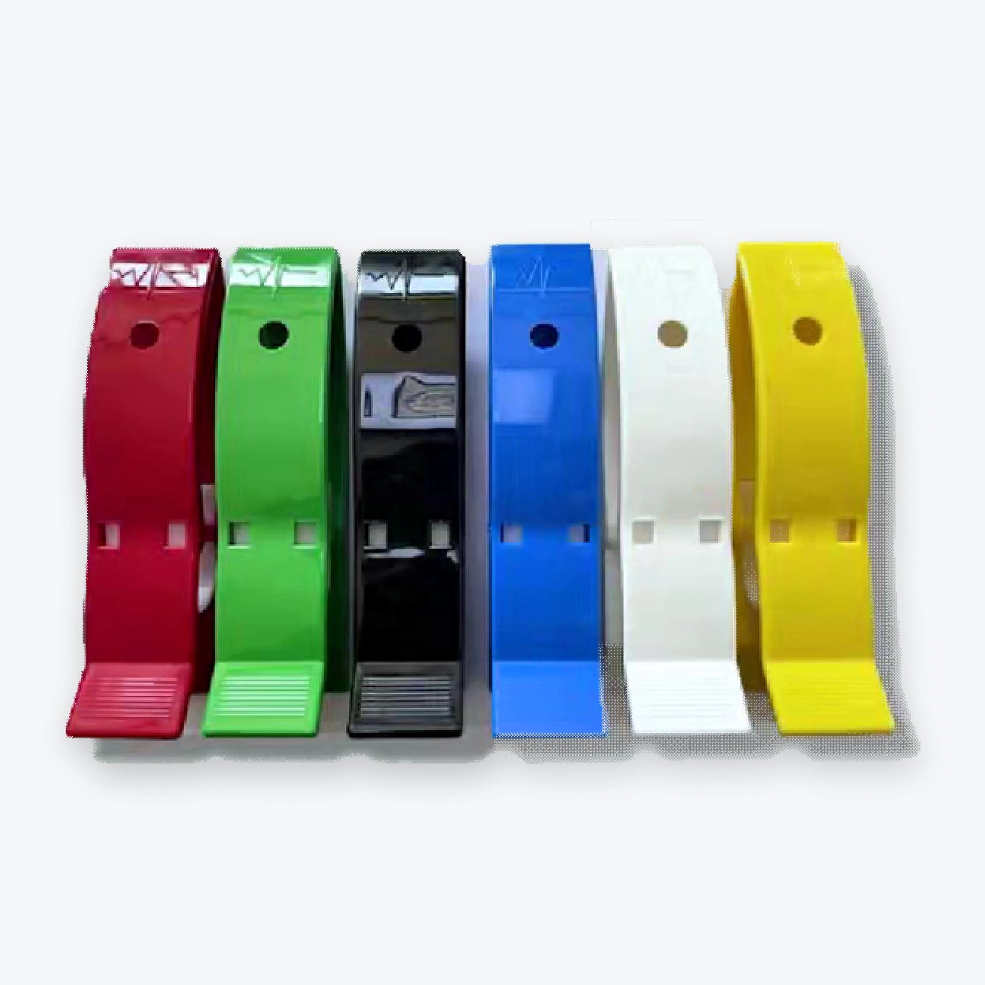
Related photographed product family: Medical Equipment Plastic Parts.
A realistic component example
A curved console piece needs alignment that reflects how it locates in the real assembly. The useful exercise is to draw the mating interface, highlight critical dimensions and identify where variation can actually cause a failure. This is more revealing than a broad assertion about “precision”.
For an OEM buyer, photographs establish the class of work and a drawing establishes the contract. Both are valuable, but they play different roles. Ask for current material and finish records whenever a visible face or regulated environment is involved.
Inspection and handover
Agree the measurement state: a supported flexible panel can behave differently from a free-state part. Name the datums, the test fixture and the sampling approach. Write down how deviations are to be dispositioned.
A first article should identify the tool condition, resin information and design revision. Later changes to material, cavity geometry or coating can change a previous conclusion; change control belongs inside the production plan, not in a late email.
Practical questions for the next RFQ
Who approves the visible appearance? Does the component use a snap, threaded insert, screw or gasket? Is the piece inspected as molded or after finishing? What is the forecast and the first-batch quantity? Answering these questions helps the tooling, molding and commercial teams work from the same baseline.
Where exact dimensions, shrinkage allowances or material compliance are needed, request a project-specific review. This article is a guide to the questions; it is not a part drawing or a material approval certificate.
Decision table
| Checkpoint | What to document |
|---|---|
| Fix datum strategy, conditioning, fixture support and reporting units. | Expected result, relevant drawing reference and who signs off this decision. |
| Mating assembly | CAD, interface and allowable fit variation |
| Part approval | Trial stage, inspection and acceptance record |
← Scroll table horizontally on smaller screens →